Thursday 8 March 2012

Finished Product

So I finally got around to "finishing" my amp build a few weeks ago. What I did was:

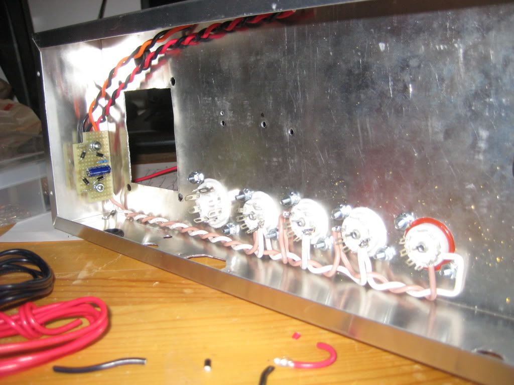
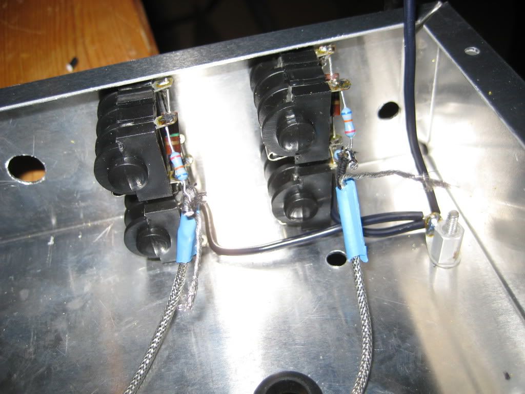
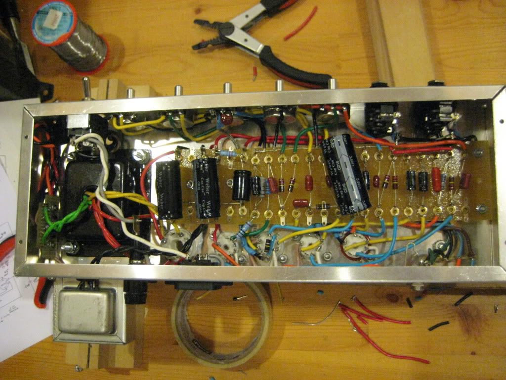
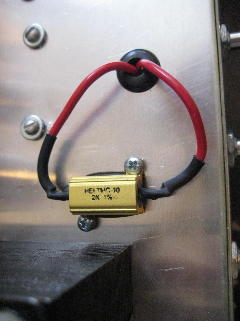
  • Swap the internal 2k bias resistor for a chassis mount version.
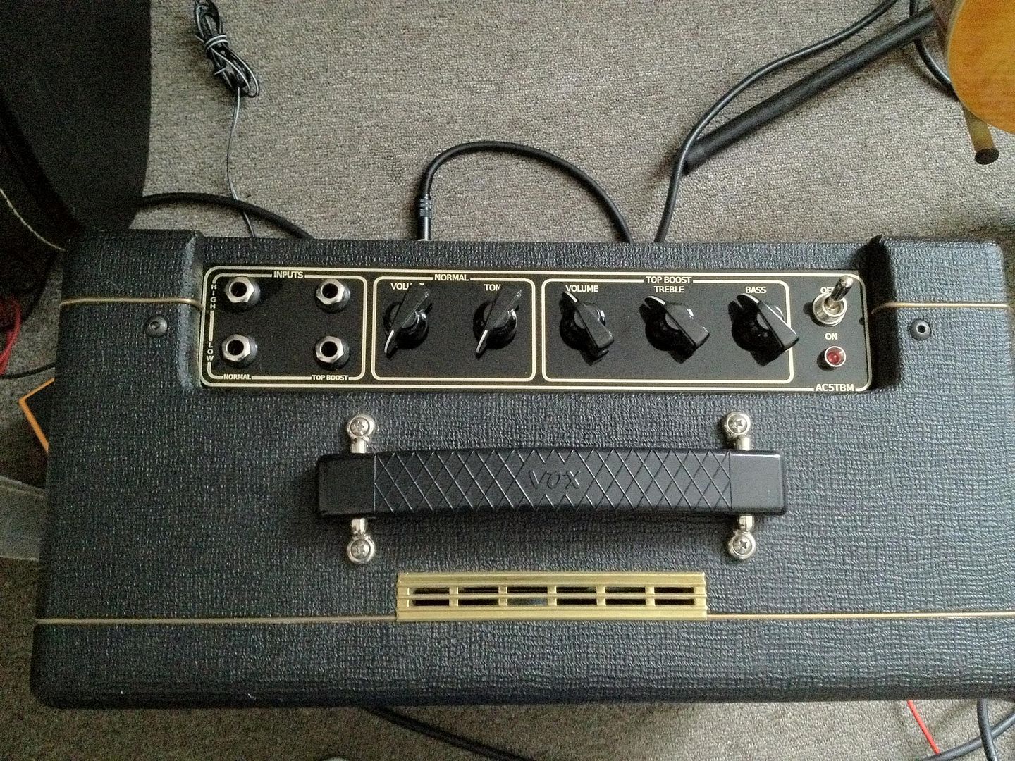
  • Installed the red indicator LED
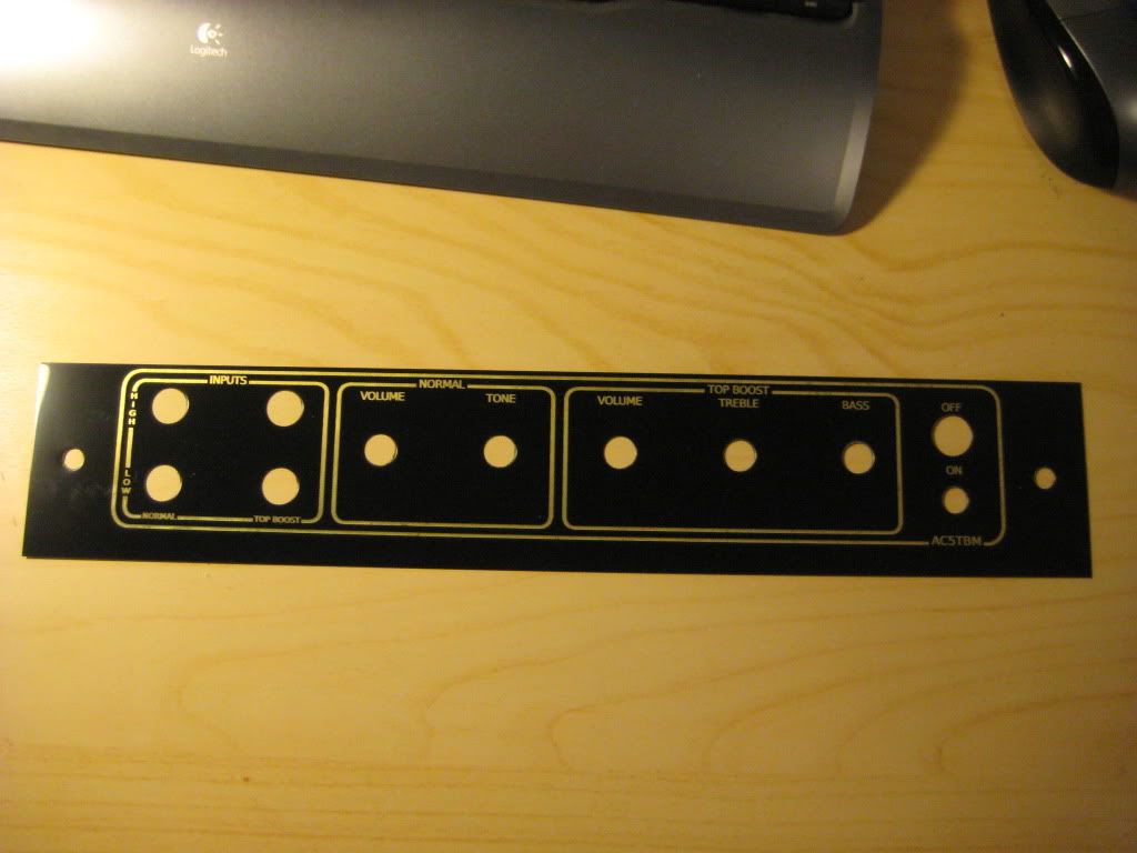
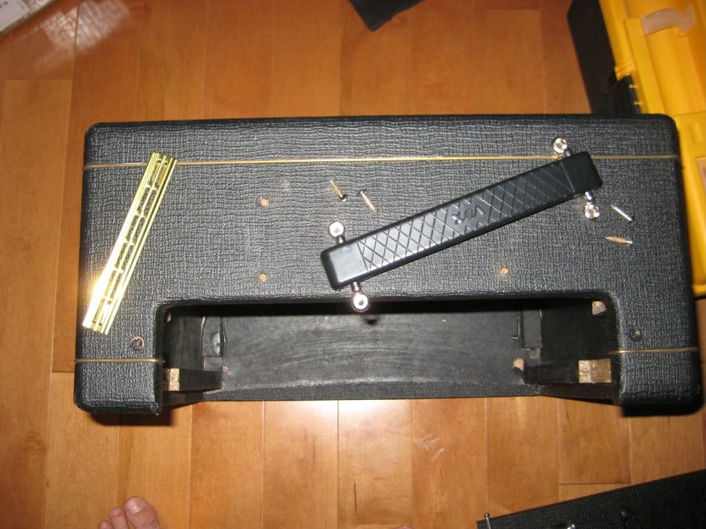
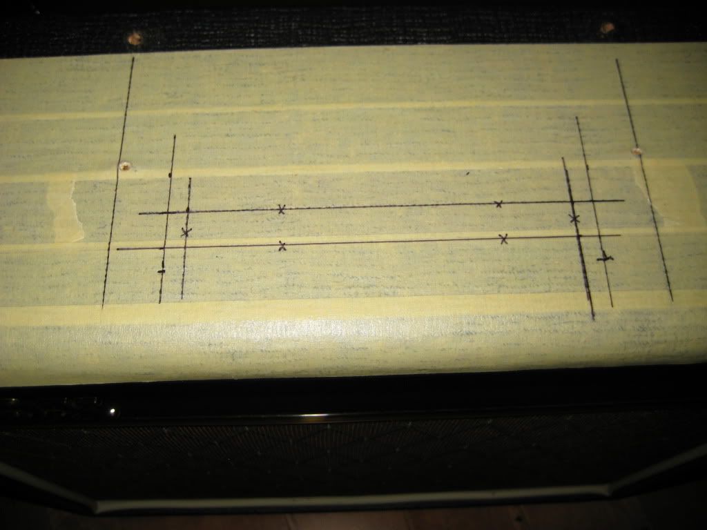
  • Bolted on the faceplate

I mounted the resistor on the exterior of the aluminum chassis in hope that I could avoid baking my electrolytic caps. If I didn't screw up on my transformer choice, I wouldn't have had to do this but the higher voltage might pay off as I mess around with different bias levels on the preamp.

The amp still gets hot. It reaches 50 degrees Celsius internal after about 90 minutes of playing. Going to go ahead with my DC fans since I already did put the wiring and socket in.

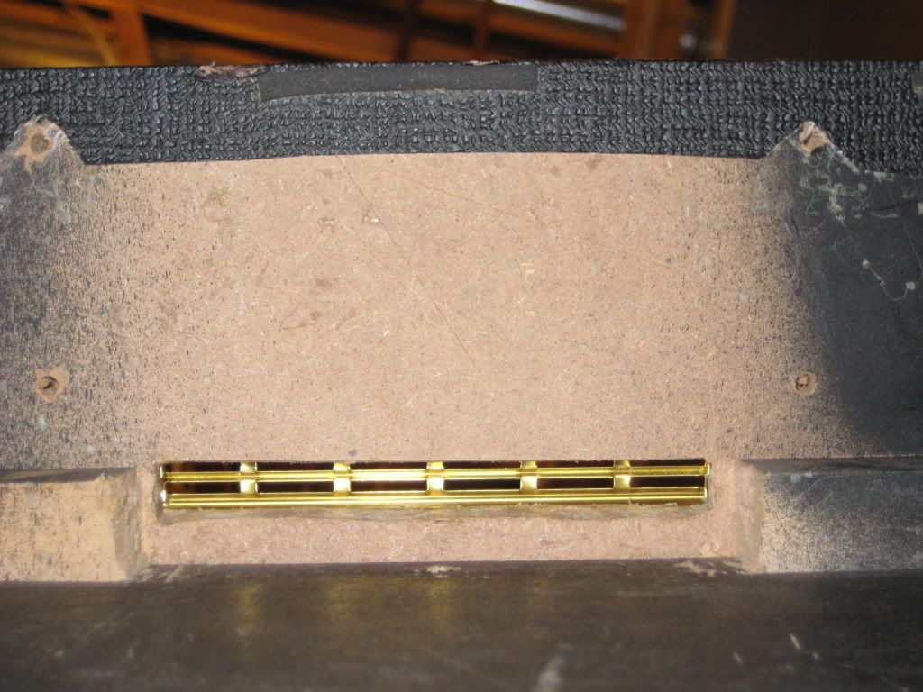
2k Ohm chassis mount resistor. 

Faceplate! Super pleased with how this turned out. Apparently I'm a master at precision guess work as all of the borders fit perfectly with the contours of the cabinet.


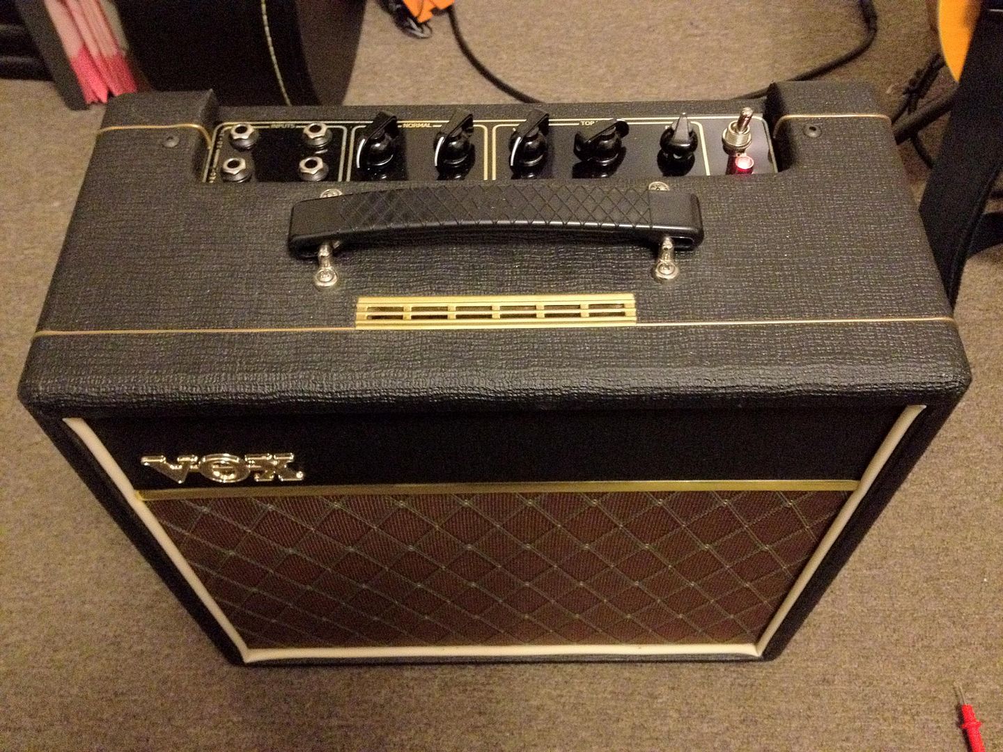
The whole package! I really can't be any happier with how this turned out. I need to get a decent microphone so that I can do this little monster some justice. 


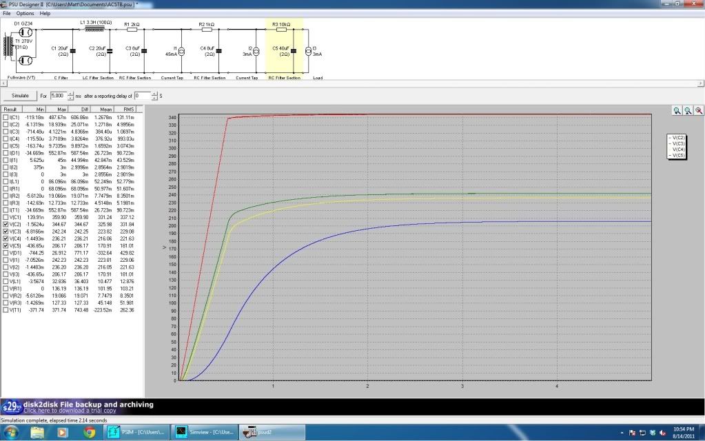
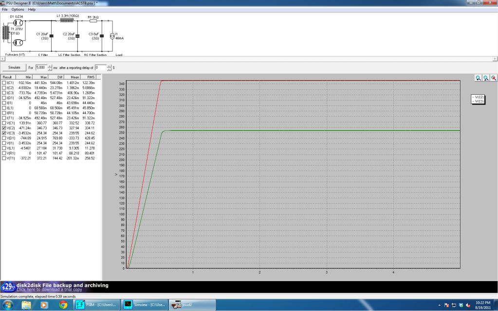
What's next? Always a tweak here and there. I'm trying to get into really modelling amplifiers using PSPICE. Being able to make a tweak in simulation is a lot better than soldering and desoldering only to find out you messed everything up. I'm all for hands-on learning but trial by fire isn't really my thing.


Tuesday 29 November 2011

Not done yet.

So it's been a while...

From actually playing the amp and I've got a change I want to make already. I'm going to change my Top Boost channel's bias. It seems to distort too much and isn't quite as loud as my Normal channel so I'm going to try to increase the head room.

There's a couple of SPICE models and whatnot floating out there so I think I might actually try and simulate my design instead of just intuition/trial and error.

FACEPLATE!

I sent this in to BNP Lasers...


and this is what I got back 2 weeks later!


I think it's pretty sweet looking. Black and gold shininess is awesome.


Anyways, back to my stupidity. Because I chose the wrong transformer, I had to use a 2K resistor to bring down the B+ voltage from ~350V to ~250V. This burns off about 5W which makes the inside of my chassis go above 40 degrees Celsius after about 30 minutes of playing time. NOT GOOD. So I'm getting a chassis mount resistor and putting it on the outside of the chassis instead where heat isn't so big of a problem. 

More on my stupidity, I wired up my input jacks completely wrong as per the diagram so that's where I was getting alot of noise from. But I think I have a tube that's on its way out because the noise now is more on the random static side.

I also realize that I owe a clip of how this thing sounds so when I get a chance to do it properly, it'll happen.

Saturday 3 September 2011

Totally Biased.

After putting in different resistors to drop the voltage on my B+ and not getting the results I wanted(i.e. too much current still flowing through the EL84 causing a low B+ voltage), I decided I was doing something wrong.

There's this term, "negative grid voltage" that keeps coming up with tube biasing but if you've never done this before, then you're probably like me and have no idea what the hell these people are going on about. Then I read Aiken's explanation of biasing found here. After about the 10th time reading if over, I finally understood what was written for my low wattage, class-A.

Basically, all of your tube voltages are measured with respect to the cathode. So if the cathode has a bias resistor, then that's going to push up positively the voltage at the cathode (with respect to chassis ground) once the current starts flowing. Now if you bring the grid connection (pin 2 on EL84) to the chassis ground, then the voltage at the grid, with respect to the cathode is negative. The more negative the grid, the less anode current will flow.

Brilliant isn't?

Now onto the hum. My layout actually seems pretty quiet. I haven't done enough poking around but the source of the hum seems to be my input jacks. There's something screwed up for sure since the low inputs don't work. Definitely a grounding issue.

Wednesday 24 August 2011

Plug and Pray

Redid my power supply with the mega voltage dropper resistor in place and I've added in a 1kOhm between the B+ and the screen grid (pin 9) on the EL84.

So my B+ has sunk down to just 175V with that 12W resistor burning off about 15W...

Anyways, I didn't really care, I finally just had to try it out now that I had traded a cherry red tube for a space heater.

There's definitely some 60Hz noise coming from possibly everywhere but it's more noticeable on the EF86 channel than the Top Boost channel. That'll be another adventure to sort out but I don't think I'm ready for that yet.

The amp isn't ear piercingly loud which is awesome! Definitely bedroom level volume.

Both channels sound pretty awesome but the Top Boost definitely stands out to me more. They both break up really nicely and there's really nothing bad to say about them. This awesomeness all came from an out of tune Squire Strat so it should only get better from here.

I guess I still have some tweaking to do but it was just nice to get a sound out of it besides the usual 60Hz groan.


Sunday 14 August 2011

Power Supply Redesign

So I really should have looked at all of the datasheets and low wattage single ended schematics that have EL84's in them and noticed that absolutely none of them go over 250V at the plate.

But I didn't so now me trying to squeeze as much power as I could out of a little EL84 has brought me nothing but a tube that glows cherry red... I guess I did get the power then, just a *bit* too much though.

Where I stand now is having to burn off about 100 Volts to get down to the seemingly magical number of 250V at the plate. So that's what I've done using the Duncan PSU Designer II.

What I came up with is this:


I assumed that each tube would draw the following current at 250 Volts across the anode to cathode:
12AX7 - 1.5mA
EF86 - 3mA
EL84 - 40mA ( Chosen using Weber's Bias Calculator )

Now, I'm still not 100% sure of what kind of current the EL84 will pull so I've ordered a whole bunch of 10W resistors to tweak the B+ levels and also some 1W resistors to fiddle with the cathode bias.

One thing though, I'm not looking forward to dealing with the heat that the 10W resistors are going to give off. Another vent might be called for. But I just want to get this thing running properly first.

EDIT: I've removed the 1K ohm dropper resistors for 2 reasons. 
1) There's already a low enough voltage caused by resistors at the plates of the preamp tubes.
2) I don't have enough room to put them :P


Putting it all together.

Wiring, lots of it. Started off by installing the tube sockets.


Ran the filament wires, the DC wires for the fan and for the indicator LED on the front panel.

Installed the input jacks.


Removed any wires on my power transformer that I didn't need (International Voltage Windings).
I cut and sealed off the ends with heatshrink, and tucked the wires into the end bells.


Installed the power transformer.


Output Jack and Transformer wired to a piece of terminal strip


Added the front panel controls.


Tube socket prep work.


The signal board. The less soldering I have to do in the chassis, the better off I'll be.


Installed the signal board, things getting messy inside. Next time, I'd get a bigger chassis.


All wired up.


SO. The Results!
Well I put power to it slowly when I was wiring. Filaments are good, DC voltages are good on the LED and fan circuit.
The B+ is around 320V where I planned for it to be. However, by measurements, I'm running the EL84 at around 44W total plate dissipation and it should be 12W... Oops?. It turns a nice cherry red right now and I'm surprised nothing has burnt on me yet.
So I'm redoing the power supply.
If things work the first time, you've done something wrong. Completely normal for things NOT to work the first time.

Thursday 28 July 2011

A Vent?

Tubes get hot, that's just how they work unfortunately. Since I'm not mounting them vertically (upside-down or right-side up) and because there's no where for the heat to go, I need a vent to keep things under control.

This is the part where if you screw up, everyone's going to notice because IT'S VISIBLE. Your sketchy wiring, crappy parts, make shift sockets...all that stuff you can hide away inside the cabinet. There's no hiding this though.

Tools I used:

  • Drill and drill bit set up to 1/4"
  • Wood files (Rasp works really well)
  • Utility Knife
  • Square
  • Chisels
  • Hammer
The before surgery shot.

All marked up and ready to go under the knife. I've planned for the edge of the vent to overlap the gold decorative tubing but not more than it has to. Again, the masking tape is to protect the area around where I'm working but so that I can also see where I need to cut.


 Surgery begins by cutting back the black tolex/vinyl outside. Just need to make the centre line again and drill along that.

From there, it's just taking the file and working until you're happy with the fit and the vent size. Patience is very important here. I accidentally cut into the decorative gold tubing and it came right off. I managed to glue it back in place with some clear silicone based adhesive that's made for kitchen and bathroom use. So it sticks really well to plastics, wood and metals.


Looks good until you zoom out and realize...
It's not symmetric. Shit.

This vent sits right in between the handle brackets so you REALLY want it to be symmetric with it. It turns out I was 1/16" off my mark and even that was enough that my eyes caught it. Obviously I had to fix it now that I noticed it.

After I made the slight adjustment, I glued it in place with the silicone adhesive I used on the piping. Can't use too much otherwise it will seep through the cracks and you'll never be able to clean it off. So use it sparingly.


Clamps off and things look absolutely amazing!


From the inside looking out, I had to take a good chunk out of one of the braces to make room for a potential fan I might have to install. I wanted a nice flat, clean looking area for fans in case I need one. Hammer and chisel served their purpose to do that.